Karnaugh Map Simplification
The Simplify the boolean function using K-Map Method and
inplement using basic gates and NAND gate prepare the
truth table and Verify.
Components Required:
Digital Logic Trainer Kit
IC# [74LSo8] [74LSB2] [74LS04]
Connecting Wire and Power Supply.
Circuit diagram Using Basic gate:
Truth Table:
|
A |
B |
C |
B |
AB |
AC |
AB + Ac |
|
0 |
0 |
0 |
1 |
0 |
0 |
0 |
|
0 |
0 |
1 |
1 |
0 |
0 |
0 |
|
0 |
1 |
0 |
0 |
0 |
0 |
0 |
|
0 |
1 |
1 |
0 |
0 |
0 |
0 |
|
1 |
0 |
0 |
1 |
1 |
0 |
1 |
|
1 |
0 |
1 |
1 |
1 |
1 |
1 |
|
1 |
1 |
0 |
0 |
0 |
0 |
0 |
|
1 |
1 |
1 |
0 |
0 |
1 |
1 |
Connection Procedure:
- Insert IC #[74LS0] (NOT)[74LS08] (AND)[74LS32] (OR) in the bread board.
- Connect Pin #7 to Ground and pin#14 to the Power Supply.
- Connect Pin #1 of NOT gate to Pin #2 of NOT gate ( short circuit ).
- Connect Pin #1 of AND gate to the First input A.
- Connect Pin #2 of NOT gate to Pin #2 os AND gate th the Second input Switch B.
- Connect Pin #4 of AND gate to third input switch c.
- Connect Pin #5 of ANG gate to third input switch c.
- Connect Pin #3 and Pin#6 of the AND gate to pin #1 and pin # Or gate.
- Connect Pin #3 of OR gate to the output switch Led.
- Verify the truth table Possibilities.
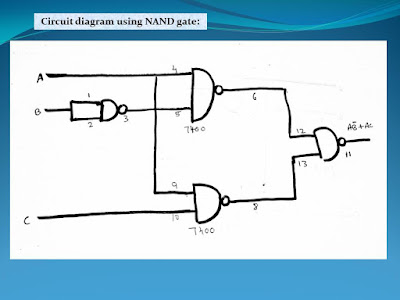
- Connect IC #74LS00 to the bread board.
- Connect Pin # to AND and Pin#14 to power Supply E.
- Connect Pin #4 as First input Switch A.
- Connect Short Circuit pin #1 and Pin #2 and takes second input Switch B.
- Connect pin #3 to pin #5 Directly.
- Connect pin #9 to pin #4 Directly.
- Connect Pin #10 to directly as third input switch.
- Connect Pin #6 tp Pin12 and Pin #8 to Pin #13.
- Connect pin #11 to the Output Switch Led.
- Verify all the truth table Possibilities.
RESULT:
Thus the Karnaugh-Map Simplification For the given Function is Verified.


No comments:
Post a Comment